Executive Summary:
A new modification to centerfire cartridge cases delays the release of the projectile from the cartridge case. This delay increases the rate of travel down the barrel and in turn, elevates muzzle velocity. There is no increase in chamber pressure. External ballistics of these projectiles have a flatter trajectory, shorter time to target and increased deposition of kinetic energy into the target over projectiles without this modification.
Introduction:
Before a firearm is fired, the cartridge, the chamber holding the cartridge and the barrel all are at rest or zero pressure. When the primer is struck by the firing pin and ignites its mercury fulminate granules, a slight pressure is created in the cartridge case’s primer pocket (Fig. 1). This is primary ignition. Then the burning granules ignite the powder in the cartridge case which leads to further increase in cartridge case pressure and in turn leads to an increase in chamber pressure. This is secondary ignition. The cartridge case flattens against the chamber wall leading to a swelling event against the chamber wall sealing the gases from exiting rearward.
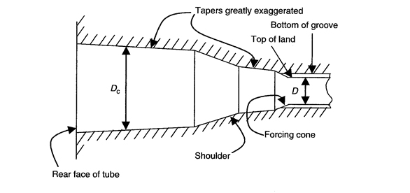
Figure 1. Cartridge case swelling against chamber wall preventing gases from escaping to the read1.
The barrel pressure comes into play when the projectile enters the barrel1.

Figure 1. Pressure vs time curve used in the calculation2. Note the early estimated pressure rise in the primer pocket. Then the primer pocket and brass see the same pressure. At 0.001025 seconds the pressure goes to zero and at 0.0011 the contact surfaces are removed so that at 0.00121 the brass is free standing.
The burning powder acts as a pressure generator. When the volume is constant, the pressure goes up at a certain rate – depending on the burn rate of the powder. But when the volume increases; the generator either (A overcomes the increased volume, (B equals the increased volume or (C is unable to keep up with the increased volume. With (A, the pressure increases. With (B, the pressure plateaus or with (C the pressure goes down.
In the early stages of powder ignition, the pressure generator (burning powder) is greater than the increase volume thus the pressure increases. So (A describes the event. However as the pressure generator slows down and the expanding volume nullifies the pressure increase, there is a pressure plateau. So (B describes the event. With further pressure generator slows down and the volume continues to expand, the pressure goes down. So (C describes the event.
Where is the projectile in relation to the three events? The literature is sparse in answering this question and what literature that does exist measures elapse time versus increase in pressure. This is further complicated by what pressure is being measured; i.e., cartridge case vs. chamber vs barrel? Generally, all are included under chamber pressure. But there are two pressure generators: a) mercury fulminate and b) cartridge powder and to my knowledge the distinction is rarely made. Even so, we do know the mercury fulminate pressure generator alone has been shown to push a projectile into and out of a barrel. The examples have a number of variables associated with them; i.e., caliber, pistol vs. rifle, type of primer etc. and I suspect exceptions exist that have never been published.
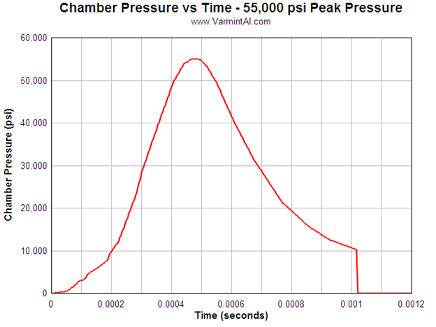
Figure 2. 6PP chamber pressure vs. time curve — peak pressure of 55,000 psi3. Note the three blue arrows. The bottom represents pressure generated by the primer. The one above it represents the beginning of pressure buildup when the primer granules ignite the gun power. The top represents when the projectile neck clears the case with full burning of gun powder. Arrow on the left represents when the projectile left the barrel.
Even though the internal ballistics may vary with caliber and weight of projectile, some generalizations can be made. With large rifle calibers, a projectile started to engage the land and grooves during the very early build up cartridge case/chamber pressure (CCCP). The base and boat tail of the projectile are still within the neck of the cartridge case (Fig. 2) when full powder ignition takes place. Next the projectile is in the first third of barrel as pressure increases.
Return to the time the projectile enters the lands and grooves of the rifling. Using Figure 2 graph as a gauge that occurs between 3,000 to 5,000 psi. What would be the results if the projectile entered the rifling between 10,000 to 15,000 psi? It would move through the barrel at a faster velocity than at the lower psi. We envision the final pressure peak would remain at 55,000 psi but the projectile would leave the barrel at a higher muzzle velocity than with the 3,000 to 5,000 psi.
LOGIC BEHIND THE INVENTION:
In order to achieve a higher velocity within the barrel, the projectile’s mid-piece and boat tail would have to remain in the cartridge case’ neck a longer time until the pressure builds up to a point where the projectile would leave at a higher velocity. The invention is a new crimping design between the cartridge neck and the projectile’s mid-piece.
HISTORY OF CRIMPING WITH CARTRIDGES.
Two of the lesser-known features of modern cartridges are cannelure and crimping. A cannelure is a groove around the circumference part of a projectile while a crimp is a compression of the case wall onto the projectile; either the complete circumference of the projectile or individual circular spots or short bands. Some case walls are “thinned” and the crimp is placed on this thin portion. The crimp can be indexed over the cannelure or if the projectile does not have a cannelure crimped onto the surface of the projectile. Cannelures can be trace back to the Civil War on the mini balls while crimping can be traced back to the introduction of semi and full automatic firearms.
The purpose of crimps, with or without cannelures is to stabilize the projectile in the cartridge case so that it does not move into or out of the case before shooting. The best examples of this happening are shipping to the battlefield or while the cartridge is in a magazine or belt with semi auto or full auto firing. Another example is with revolvers – projectile not moving forward to prevent the rotation of cylinder. During the black powder days, the cannelure served the purpose of holding grease to lubricate the barrel but this is no longer the case.
After an extensive search, there is no scientific evidence that crimp along with groove or cannelure has any other function that keep the projectile in place. I have found speculation that crimps and cannelure have additional functions, but with their existence of 150 plus years no other function has been found supported by scientific evidence. Crimp and cannelures are to keep this projectile in place4 .
INVENTIONa:
The invention requires modifying the projectile as well as the neck of the case (or just the case if there is no neck) so that a circular groove of a known depth and width are made circumventing the projectile (Fig. 3). A crimp of a known depth and width to the neck (or case if there is no neck) is made over and into the groove. The purpose of the crimp is to restrict the movement of the projectile to a cartridge pressure that would be higher than required without the crimp. The result is that the projectile enters the barrel at a faster velocity than without the crimp. Types of crimps:
- One 360 degrees crimp
- Two crimps at zero and 180 degrees
- Three crimps at 120, 240 and 360 degrees
- Four crimps at 90, 180, 270 and 360 degrees
- Crimps at any configuration where the projectiles leaves the neck (or case if there is no neck) of the case evenly – not off balance.
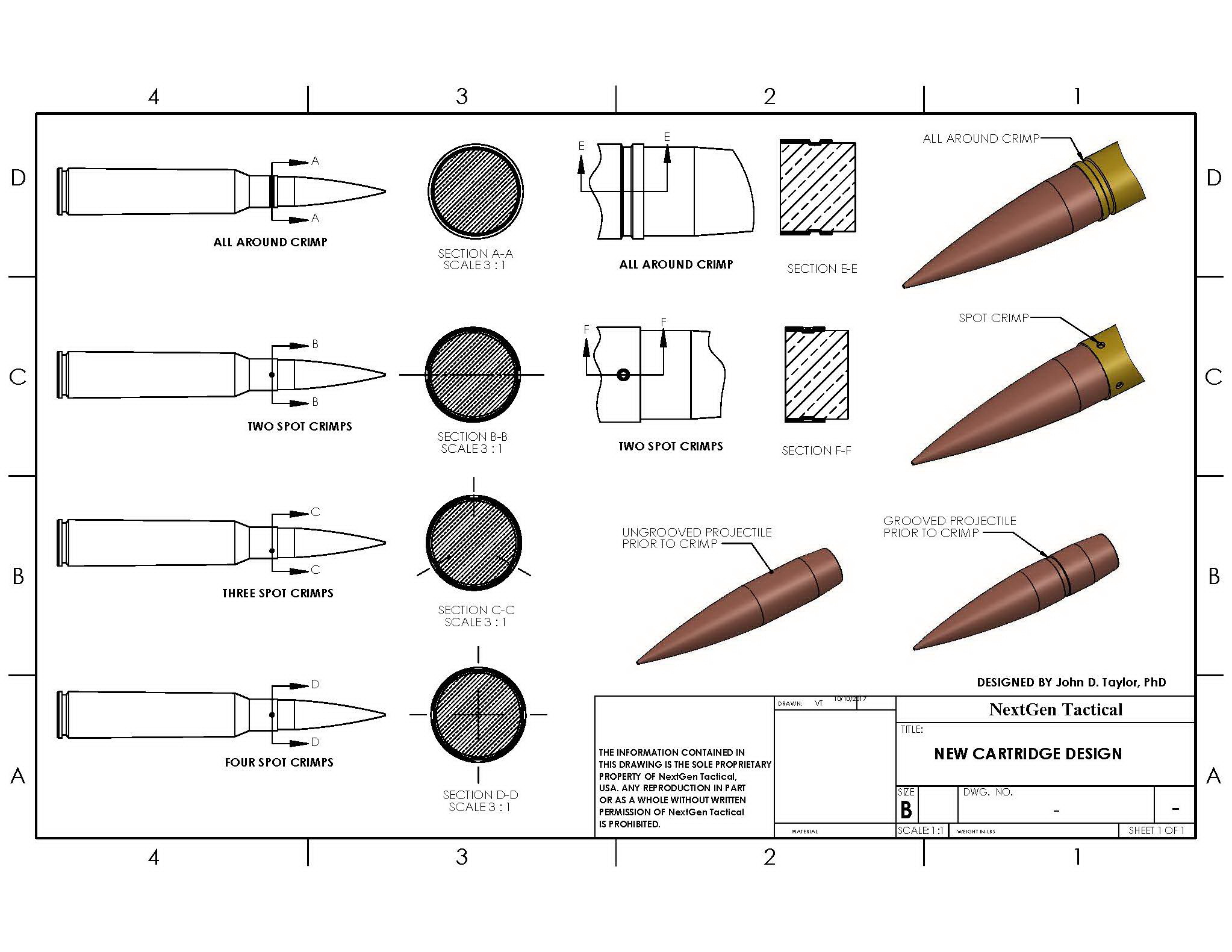
Figure 3. Composite illustration showing the diverse types of crimp in relation to the projectile with a circular groove and the neck of the cartridge case where the two types of crimp a) 360 degree and b) spot crimps at the following locations: i) 12 and 6 o’clock, ii) 12, 4 and 8 o’clock, iii) 12, 3, 6, and 9 o’clock. Whether a circular or a spot crimp the neck of the cartridge case is crimped into the groove surrounding the mid piece of the projectile.
NOTE: Nothing is said here regarding the pressure to make the crimps. That will have to be determined by experimentation. In addition the final number of crimps may not be limited to those outlined in i), ii), and iii) above. The final number will be determined by experimentation.
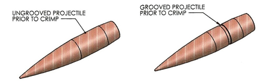
Figure 3a. Two projectiles. One with without a groove while with a grooved at the midpiece.
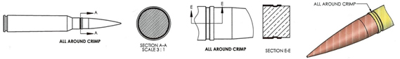
Figure 3b. From left to right. 360 degree clamp with section AA. X section of projectile showing section AA. Dark line is bottom of clamp while thin line above is wall of clamp. EE shows lateral view of clamp into groove. Next image is sagital section view showing clamp into groove. Last image is 3D view of forward end of cartridge.
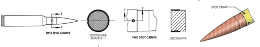
Figure 3c. From left to right. BB shows two crimps – one that you can see and the other is on the other side of the cartridge. Section BB shows two crimps – line going through them. The light line represents the wall of the crimp while the line is the bottom of the crimp. FF shows one of the two crimps – the other is on the other side of the cartridge. Section FF shows sagittal view with crimp at 12 o’clock and one at 6 o’clock. Thin line represents wall of crimp while the talk line represents bottom of crimp. Last image is 3D view of forward end of cartridge showing the two crimps.

Figure 3d and 3e. Images using same logic to show three and four crimps. As previously, thin line represents the wall of the crimp while the thick line represents the bottom of the crimp.
BURNING RATES OF GUN POWDER
The burning rates of gun powder are relative and do not have a basic unit of burning. Some burn very fast whiles other burn medium and lastly still others burn slow. These are put into a chart with the slowest to the fastest. As a general rule pistol powder burns fastest, magnum pistol burns medium and the high velocity, big bore burns the slowest. The invention, number of crimps and indexed over the groove will have to be determined for caliber. The invention is made for the high velocity, big bore rifle calibers as the burning rate is the slowest. The result is the projectile does leave the cartridge case at a higher pressure than normal which results in more of the powder is burned, thus reducing flash and exits the barrel at a faster muzzle velocity.
Without the invention, most of the powder is still burning as the projectile leaves the muzzle resulting in a large flash. This powder contributes little to medium of the muzzle velocity, depending on the burn rate and can be considered wasted. This is the reason for flash suppressor, connected at the front of the barrel – reduces flash by cooling or separating the burning powder from one another; i.e., gases that exit the muzzle a phenomenon typical of rifles with short barrels.
SIGNIFICANCE OF INVENTION
The invention delays the release of the projectile from the cartridge case. As a result, chamber pressure increases before it exits the cartridge case plus the expanding volume behind projectile in the barrel.
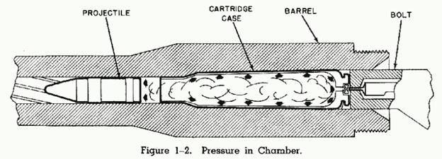
Figure 4. Arrow points to the space between projectile and cartridge cases. The early stages of the expansion of chamber pressure volume.
With time the cartridge case volume plus the volume behind the projectile increases as it goes down the barrel on its way to the muzzle. This delayed release of projectile from the case insures further burning of powder and thus increase in chamber pressure. At the same time, more of the powder is burnt than without the invention thus reducing the flash as the projectile leaves the muzzle. Finally the projectile leaves the barrel faster than without the inventions.
As the volume of case plus the case expanding volume behind the projectile will results in a plateau of peak pressure rather than a sharp peak pressure thus resulting in chamber pressure not elevating which would be the case without the invention.
John D. Taylor, Ph.D.
Professor Emeritus
Fellow, AAAS Emeritus
October 22, 2017
ACKNOWLEDGMENTS:
The author would like to thank Victoria Trafka, MS ME, Engineering & Quality Solutions, Inc. for SolidWorks contributions to the research with this project.
aTaylor, J. D. and D. Omanoff. 2019. Cartridge arrangement for increased muzzle velocity of guns. European Patent Office. EP3569972A1
References:
1Carlucci, D. E. and S. S. Jackson. 2013. Ballistics. Theory and Design of Guns and Ammunition. p 120. CRC Press (Taylor and Francis Group. Boca Raton, FL.
2Varmit Al. 2013. Finite Element Analysis (FEA) of a Remington Model 7 in .243 Win Caliber Using The LS-DYNA Software. https://www.varmintal.com/amod7.htm
3Varmit Al. 2015. Rifle Chamber Finish & Friction Effects on Bolt Load and Case Head Thinning. FEA Calculations done with LS-DYNA. https://www.varmintal.com/a243z.htm
4Hayden, R. D. and T. C. Almgren. 1995. Sierra Rifle Reloading Manual, 4th Ed.