EXECUTIVE SUMMARY:
A review of rotating projectiles in flight (External Ballistics) is described. Next the physics behind Balance Flight design (Generation One) which is critical for accuracy at extreme long-range distances is reviewed. This is best exemplified by the .375 & .408 CheyTac® calibers. The focus of this article is to extend Balance Flight, Gen 1 to the next generation, Gen 2, which expands the success of .375 & .408 CheyTac® to cover multiple calibers.
THE PHYSICS OF ROTATING PROJECTILES WITH MOTION:
A projectile begins its flight once it emerges from the bore of the firearm. The signature of the projectile’s trajectory in flight is influenced by factors associated with the projectile itself, some associated with the atmosphere in which the projectile translocates and some associated with the earth’s gravitational forces. A projectile’s mass, diameter, shape as well as axial spin rate are characteristics that influence its trajectory signature in flight. These characteristics are only important when viewed in relation to a defined speed of the projectile. If the projectile travels far enough without first hitting a target, it will experience three speed zones: supersonic, transonic, and subsonic. Conditions in the atmosphere affect speed. It is a fluid with varying characteristics including its density, temperature, viscosity, and wind direction. Speed in flight is measured as a value called Mach (M).

Projectiles with a Mach speed less than 0.8 are subsonic, while those greater than 1.2 are supersonic. The range between the two values is known as transonic. This is depends on the altitude of the projectile.
In a vacuum, gravity is the only force acting on the projectile in flight. However, in the atmosphere, the projectile encounters resistance called drag or drag force. Drag depends on the forward speed of the projectile – at high speeds, it is the dominant force influencing the projectile. Drag has a major influence in modifying the trajectory signature during the early part of the trajectory arc and minor influence occurring during the latter part of the trajectory arc.
There are five factors that separately contribute to drag force:
- Skin friction
- Pressure drag
- Base drag
- Wave drag
- Yaw-dependent drag
Skin friction results from the viscosity of the fluid. Viscosity is defined as the resistance of the shearing motion of the fluid. When a projectile moves through the atmosphere, molecules immediately adjacent to the surface cling firmly to the surface while those adjacent to the surface flow parallel to it. So, there is an area where shearing occurs, i.e., boundary layer. This contributes to pressure drag.
The average static pressure at the front of a projectile is greater than that found at the end of the projectile (Figure 1).
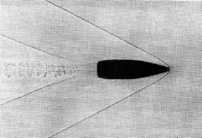
Figure 1. Note Pressure & tail waves.
This is called pressure drag. Pressure drag can be reduced if the front of the projectile is pointed and the base is tapered. Even so, a base drag can develop because of the fluid moving around it to form a wake. These characteristics are pronounced at subsonic speeds and reduced at supersonic speeds. Another drag appears at supersonic speeds, i.e., wave drag. This is due to the shock waves generated by the projectile traveling through stationary air at a speed greater than the speed of sound. If the shape of the projectile changes dramatically from its forward tip, an additional shock wave will be produced resulting in an additional drag. The total drag is the sum of all drags. Taking into effect the air density and forward speed of the projectile, a value without units can be determined. This is drag coefficient. Drag coefficient is used as a measurement of projectile efficiency during flight depending upon the speed of the projectile.
A projectile will not travel with its axis aligned to the direction of flight. A measurement called the yaw angle is the angle between the projectile axis and the direction of the flight (Figure 2). Causes are numerous, but this results in a force impinging upon the side of the projectile, which contributes to drag. The level of drag is related to the angle of yaw.

Figure 2. Yaw angle.
On the other hand, the rate at which projectile velocity decays against a standard is called ballistic coefficient. The ballistic coefficient is expressed as a measure of mass per unit frontal area of a projectile times a drag efficiency factor. The projectile deceleration is inversely proportional to it. The larger the ballistic coefficient means the smaller the deceleration. The stability of a projectile in flight is related to its ability to overcome disturbances. For example, a projectile subjected to yaw disturbances will define its stability. The projectile might tend to tumble when the center of pressure is forward to the center of gravity. The projectile cannot return to a stable state. Other examples of instability exist. There is an important correlation in the distance between the center of pressure and the center of gravity and its relation to the stability of the projectile. This is called static stability of the projectile. Most projectiles are aerodynamically unstable in flight. This can be overcome however, by the incorporation of axial spin. For example, if a projectile is experiencing a nose upward motion resulting in an increased yaw angle, a projectile spin – assuming it is fast enough, will cause the nose to move to a stable position or back to its original yaw. There is a second motion present – one in which superimposes the first. This is gyroscopic motion known as nutation. This motion of a projectile in flight is determined by the dynamic stability of the projectile. Upper and lower limits exist for the rate of spin. Too much spin results in a projectile flying at a larger yaw angle, which results in loss of the distance traveled and accuracy. Spin rates with projectiles with small diameters are high. In addition, a longer projectile is more difficult to spin versus a shorter projectile. Finally, projectiles entering tissues will become directionally unstable and will tumble. This assumes that they retain their original shape.
BALANCE FLIGHT GENERATION ONE: A NEW DESIGN THAT INHANCES ACHIEVED DISTANCE WITH GREATER ACCURACY
The Balance Flight design for rotating projectiles was first presented by Warren Jensen in 2001 in a patent entitled Controlled Spin Projectile1 which led to the success of the .408 CheyTac® cartridge achieving first shot hits at 2,400 meters (1.5-mile) plus2,3,4, which in turn, opened the military field of extreme distance sniping.
The logic behind Balance Flight design was to stabilize the projectile in flight to achieve maximum performance. A projectile being able to retain stability throughout its flight will go farther and will be more accurate. Conditions were identified that could be translated into projectile design, which would exhibit extreme distance accuracy. The concept is called Balance Flight and is based on PRODAS (Projectile Rocket Ordnance Design & Analysis System) software by Arrow Tech Associates Inc5. Working with PRODAS software, projectiles were designed where the linear drag on a projectile is matched to its rotational drag. In other words, forward rate of deceleration and an axial rate of deceleration are balanced. The gyroscopic stability remains constant resulting in the projectile remaining on its original trajectory path. This was confirmed with Doppler Radar at the U.S. Army Yuma Proving Grounds and was reconfirm at a second visit to the Proving Grounds. On both visits, the radar technicians indicated the .408 CheyTac®was the only two examples, after reviewing the trajectory of tens of thousands of other projectiles, the .408 CheyTac® projectile never left its original trajectory path as it slowed from supersonic to transonic and then into subsonic.
Non-Balance Flight occurs when a projectile’s spin is too great, thus leading to an “over spin” of the projectile. Over spin leads to projectile destabilization — first expressed as projectile yaw, then to projectile tumbling, then to the projectile leaving its original trajectory path and finally the projectile falling to the ground (Figure 3).

Figure 3. Stability in flight
A vital component of Balance Flight is the design of the barrel lands and grooves. A ratio of a total surface of the projectile to a total surface area of the physical feature in the range of to 3.00:1 to 4.00:1 is critical. As a result of projectile and barrel land / groove design, the drag coefficient is reduced to a range of 0.100 to 0.250. In addition, the bearing surface of the projectile has a depth equal to 1% of the caliber of the projectile and a ratio of a total surface area of projectile to the total surface of the physical feature in the range of to 3.00:1 to 4.00:1. The purpose is to impart an ideal axial surface friction upon launching, which during flight produces a trajectory characterized by a continuously decreasing rate of axial deceleration.
BALANCE FLIGHT GENERATION TWO WHICH INCLUDES MULTI-CALIBER TO ACHIEVE VERY LONG DIST
We (JDT & DO) took the Balance Flight very-long range projectiles design to the next generation6,7. This was based on the outstanding success of the .375 and .408 CheyTac® cartridges in the extreme long-long range tactical world. We took a “common thread of characteristics” to create a “perfect design” no matter the calibre. The evolution of design is in the measurements of these characteristics are translated into a formula that could be applied to the diameters of any projectile’s caliber. There are specific relations between the projectile’s calibre or diameter D1, overall length L compared to the length component parts: a) ogive length: L1; b) engraving surface length: L2 and c) boat tail length: L3. One embodiment shows a projectile, wherein the projectile has a solid body of revolutionary shape, the nose portion has an ogive shape having a first length L1 the middle portion has a cylindrical shape defining the bearing surface with a diameter D1 and a second length L2, and the base portion has a frustroconical shape having a third length L3. The first length L1 equals 3 to 3.5 times, preferably 3.1 to 3.25 times of the diameter D1, the second length L2 equals 1 to 2 times, preferably 1.25 to 1.5 times of the diameter D1 and the third length L3 equals 0.1 to 1.5 times, preferably 0.1 to 1.1 times of the diameter D1 (Figure 4)
| D1 | L | L (min) | L2 | L2 (min) | L1 | L1 (min) | L3 | L3 (min) |
| 0.308 (7,8) |
1.694
(43,0) |
1.617
(41,0) |
0.462
(11,7) |
0.385
(9,8) |
1.001
(25,4) |
0.9548
(24,3) |
0.3388
(8,6) |
0.0308
(0,8) |
| 0.3378
(8,6) |
1.8579
(47,0) |
1.77345
(45,0) |
0.5067
(12,9) |
0.42225
(10,7) |
1.09785
(27,7) |
1.04718
(26,6) |
0.37158
(9,4) |
0.03378
(0,8) |
| 0.375
(9,5) |
2.0625
(52,3) |
1.96875
(49,8) |
0.5625
(14,2) |
0.46875
(11,7) |
1.21875
(30,9) |
1.1625
(29,5) |
0.4125
(10,5) |
0.0375
(0,9) |
| 0.408
(10,4) |
2.244
(57,0) |
2.142
(54,4) |
0.612
(15,5) |
0.51
(13,0) |
1.326
(33,7) |
1.2648
(32,0) |
0.4488
(11,4) |
0.0408
(1,0) |
Figure 4. Schematics of the formula for multi-calibres
Embodiments, which are within the above range are given according to the following table, wherein D1 characterizes the bullet diameter or calibre, L characterizes the overall length, L2 characterizes the length of the middle portion (or bearing surface range), L1 identifies the length of the nose portion (ogive length) and L3 identifies the length of the base portion (boat tail length). In the table the values in brackets are in the metric system and show the values in millimetres (mm), wherein the values without brackets are given in inches.
John D. Taylor, Ph.D.
Professor Emeritus & Fellow Emeritus, AAAS
Dennis Omanoff, MBA
CEO, Tungsten Parts Wyoming, https://tungstenparts.com/
Date: November 1, 2022
ACKNOLEDGEMENTS: The author would like to thank Victoria Trafka, MS ME, Engineering & Quality Solutions, Inc. for SolidWorks contributions to the research with this project
REFERENCES
1 Jenson, W. 2001. Controlled Spin Projectile. U.S. Patent Office, 20020190156A1.
2Taylor, J. D. 1997. Parental Cartridge Cases: The Future. Shooter’s News, June, pp. 15-27.
3Taylor, J. D. 1998. .408 Cheyenne Tactical™ — A Novel 2,000-Meter Tactical Cartridge. Part I. Tactical Shooter, Vol. 1, No. 2, pp. 70-74.
4Taylor, J. D. 2000. .408 Cheyenne Tactical™ — A Novel 2,000-Meter Tactical Cartridge. Part II. Tactical Shooter, Vol. 3, No. 4, pp. 5-20.
5 Prodas. Arrow Tech Inc. https://arrowtechassociates.com/.\
6Taylor, J. D. and D. Omanoff. 2018. Small Arms Projectiles. U.S. Patent Office, 20190113318 A1.
7Omanoff, D. and J. D. Taylor. 2017. Small Arms Projectile. European Patent Office, EP3470769A1